

An electric current is a stream of charged particles, such as electrons or ions, moving through an electrical conductor or space.
It is measured as the net rate of flow of electric charge past a region.
The SI unit of electric current is the ampere, or amp, which is the flow of electric charge across a surface at the rate of one coulomb per second.
Current can be measured using an ammeter.
For a steady flow of charge through a surface, the
current I (in amperes) can be calculated with the
following equation:
I=Q/t
where Q is the electric charge transferred through the surface over a time t. If Q and t are measured in coulombs and seconds respectively, I is in amperes.
More generally, electric current can be represented as the rate at which charge flows through a given surface as:
Voltage, electric potential difference, electric pressure or electric tension is the difference in electric potential between two points, which (in a static electric field) is defined as the work needed per unit of charge to move a test charge between the two points.
In SI units, work per unit charge is expressed as joules per coulomb, where 1 volt = 1 joule (of work) per 1 coulomb (of charge).
Voltage or electric potential difference is denoted symbolically by V, ∆V, or U
A voltmeter can be used to measure the voltage (or potential difference) between two points in a system.
In electronics and electromagnetism, the electrical resistance of an object is a measure of its opposition to the flow of electric current.
Ohm’s law states that the current
through any conductor is directly
proportional to voltage or potential
difference between its ends, if the
physical conditions of the conductor
do not change.
I ∝ V
or I = V/R
Or we can state it as, V = IR.
This relationship between current, voltage was discovered by German scientist Georg Simon Ohm.
Ohm’s law is not applicable to unilateral networks.
Note:- Unilateral networks allow the current to flow in one direction. Such types of network consist elements like a diode , transistor, etc.
Ohm’s law is also not applicable to non – linear elements.
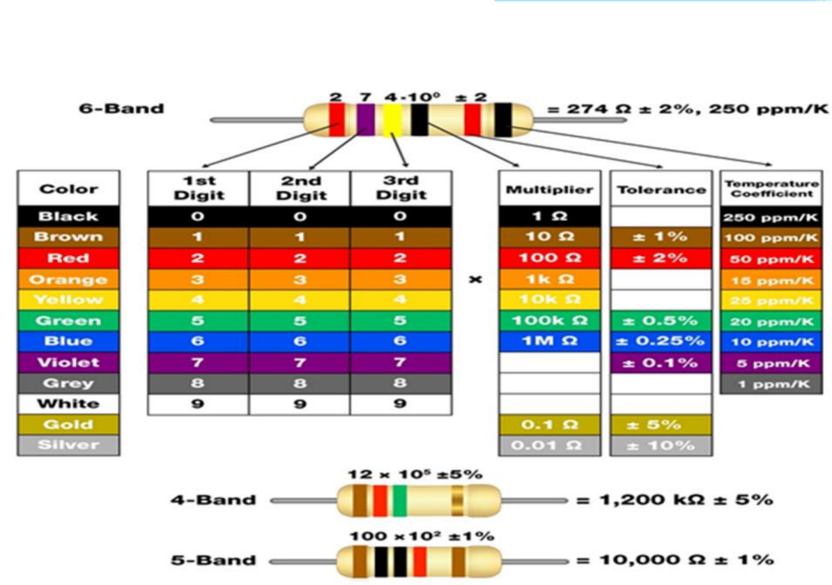
Note:- Non-linear elements are those which do not have current exactly proportional to the applied voltage that means the resistance value of those elements changes for different values of voltage and current. Examples of non – linear elements are the thyristor.A resistor is an electrical component that limits or regulates the flow of electrical current in an electronic circuit.
Resistors are one of the important blocks of electrical circuits.
Resistors are one of the important blocks of electrical circuits.

Resistance of the conducting material is calculated using
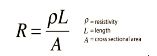
The resistance of a conducting material is found to
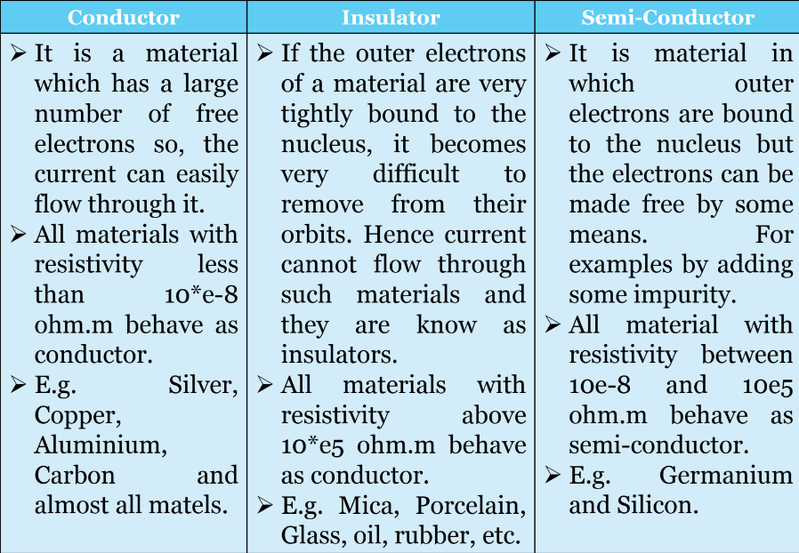
1. be directly proportional to the length L of the material.Electrical resistivity (also called specific electrical resistance or volume resistivity) and its inverse, electrical conductivity, is a fundamental property of a material that quantifies how strongly it resists or conducts electric current.
Resistivity is commonly represented by the Greek letter ρ (rho). The SI unit of electrical resistivity is the ohm-meter (Ω⋅m).
The resistance of an object depends in large part on the material it is made of. Objects made of electrical insulators like rubber tend to have very high resistance and low conductivity, while objects made of electrical conductors like metals tend to have very low resistance and high conductivity.
The resistance of an object also depends on the size and shape of an object because these properties are extensive rather than intensive. For example, a wire's resistance is higher if it is long and thin, and lower if it is short and thick.
Resistance of almost all the materials changes with the change in the temperature.
Then the change in resistance is found to be I. directly proportional to its initial resistance, and II. directly proportional to the change in temperature. • Thus, α= constant know as the temperature co-efficient of resistance.
The variation of resistance with change in temperature of any material is governed by this property.
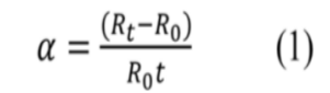
Temperature co-efficient of resistance α is defined as the change in resistance per unit rise in temperature per ohm original resistance.
Usually temperature co-efficient is taken at a particular reference temperature which is normally taken as 0 degree Celsius.
It is denoted by α0
Rewriting the equation (1), Rt = R0*[1+α0*t]
If at a standard temperature of o degree Celsius a material has a resistance of R0 ohms,
at t1 degree Celsius resistance of R1 ohms and
at t2 degree Celsius resistance of R2 ohms, then
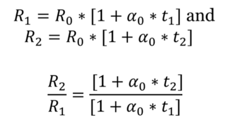
If temperature co-efficient ao and resistance Ro are not given then the relation between the known
resistance Rt1 and t₁ degree Celsius and the unknown resistance Rt2 and t₂ degree Celsius can be found
as follows:
Rt1 = resistance at t₁ degree Celsius
Rt2 = resistance at t₂ degree Celsius
Suppose,
αt=temperature co-efficient of resistance at t₁ degree
Celsius
αt1 = Slope of the graph / resistance at t₁ degree Celsius Slope of the graph= αt1* Rt1